 |
BFI 3 |
|
BFI 3 |
by Peter Scott
BFI 1 was the first BFI
BFI 2 is a little newer, more photos and instructions.
Analysing the stock Soarer Intake looks at what the standard intake is like - where improvements can be made.
Siting Cold Air Intakes The best place to take air from, analysing your own intake.
Air Filters I use the genuine Toyota Air filter - this is how it stacks up against other filters
The current BFI on my car is cosmetically more appealing. Rather than launch into a great big square hole in the middle of airbox - I wanted something that looked a bit better and was easier to do.
Removing the headlights (you'll need both of them out) is best explained here: http://web.ace.net.au/soarer/removal.html
I have not replaced the side bolts of the headlight - the top bolt by itself has held my headlight in on its own for 2 years now.
You can see the BFI 1 and BFI 2 pages here: BFI
These list how to make your own BFI and where to get all the parts.
The Soarer intake testing and development pages are here: Soarer Intakes
This latest BFI detailed here has the following features:
Remember the BFI has three full chambers for a reason - all have their functions and add to the effectiveness of the BFI. A BFI without three full chambers isn't a BFI at all. Only the full three chamber BFI makes max pressure, max flow, maximum filtration, no water and minimum bugs.
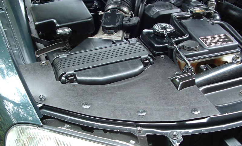
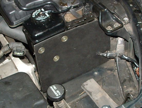
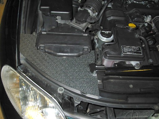
I wanted a top cover that wouldn't get a second glance - a top cover that looked almost factory. I didn't want a top cover that looked homemade, would sag with the heat, had rough edges or bolts holding it down that looked out of place. A cover that was secure, easy to remove and held firmly in place. This is what it currently looks like:
The black plastic sheet used is grained on one side. I selected it from many materials because it looks factory, has a grain, is tough and durable, cheap and readily available.
It is called Polypropylene black plastic leather grain 2mm
sheet. Doesn't warp, resists under bonnet temperatures, flexible yet stiff
enough, very tough, floats and can be cut with big scissors. I used a jigsaw cutting the
inside curves. Sand edges afterwards for smooth look.
In Yellow Pages ( http://www.yellowpages.com.au/)
look up
Plastics-
Products-
W'salers & Mfrs
and ask for it. Some places will stock it, others will say they have to get it in. Just
pick up the phone and give it a go.
I bought a rectangular sheet (1m by 0.5m roughly) for $15 - great stuff.
It's smooth on one side and has a leather (also called hair cell) grain on the other -
looks very presentable. One sheet is enough for top plate, under headlight plate, shield
on side of airbox, and to seal off the battery side headlight hole and still have lots
left over.
The scrivets (black plastic fasteners) are low profile, look great, and are available on
the handy rack at auto parts stores - $2 for 5. Same place as the christmas tree plastic
clips and rubber grommets etc.
The top cover is discreet - hopefully no one will notice it.
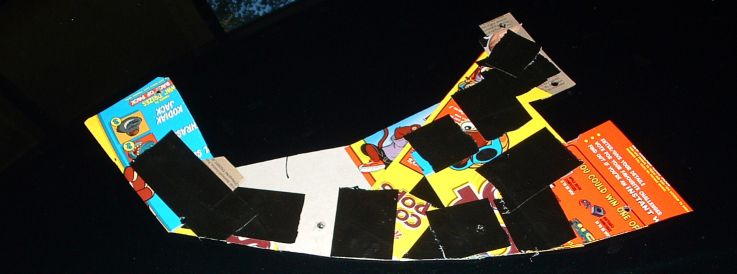
Making it can be straightforward if you take your time - rush it and you'll be disappointed. I made a template using just cardboard and tape. I kept taping together bits of thin firm cardboard in place, cutting them with scissors as I went, poking the holes with a screw driver etc - until I had the shape I wanted:
The cornflakes packets are best in the family size - gives nice piece of cardboard to make
a template - get template right and the rest is easy. If you want an extra bit of pep try
the cocapops, four bowls of that stuff to empty the stupid pack so you can use the outside
packaging will get you going for sure.....
In this picture above you can see the many bits of cardboard I used all stuck together
with black tape. Then I punched the holes in place. The I traced the shape to the black
polyprop sheet and carefully cut it out - I was so happy with my first attempt I have left
it in place - it is not perfect - just a first go prototype.
So that's the top cover done.
The other large area worth sealing is that big hole on the engine side.
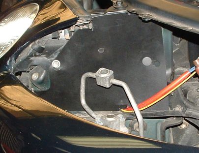
Again nothing fancy this time - I used the same plastic sheet and made a simple square - I used the three existing bolts. The rubber spacers already there moved this sheet out nice and close to the airbox - it doesn't move, looks neat and is easy to make and near invisible with cover in place. I have re-routed some of the wiring - the oil level sensor for the power steering has been unplugged, and moved to the other side of the metal bar.
I really don't think it is worth insulating the airbox or any parts of the intake system. I do have a differential air temp sensor - another autospeed project. I'll hook it up and compare the temp of the intake system compared to outside.
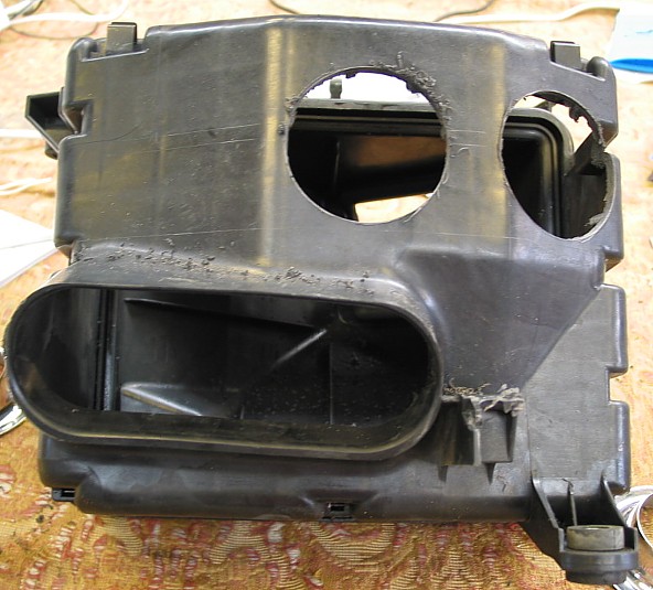
The previous BFI airboxes had a big square hole cut out of them. You can see them on BFI 1 and BFI 2. Another one is described here: http://web.ace.net.au/soarer/bfi.html.
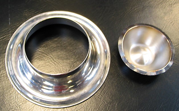
Using a hole saw is easier than cutting the whole front of the airbox out. But after cutting a round hole I wanted a neat edge to it. The autospeed.com article on Ballistic Bellmouths was my inspiration - another great idea by Julian Edgar. By using an eggcup from Woolworths (also called Safeway in Vic) (cost of $1.50 has now gone up to $2! - but still cheaper than the $40 at motorsport shops) and grinding the bottom of the cup off using a bench grinder.
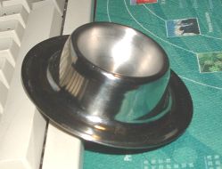
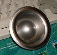
The regular eggcup on the left - the underside makes a great bellmouth - just need to grind away the top part. Look much neater installed in airbox than just a plain hole.
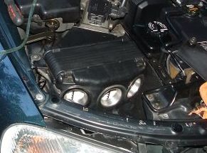
I installed two of them in the airbox fist of all - I wanted to see if that would be enough.
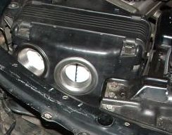
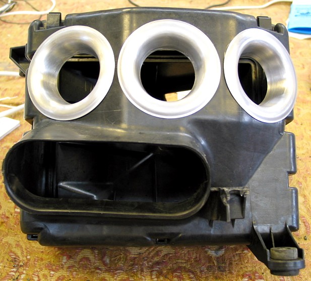
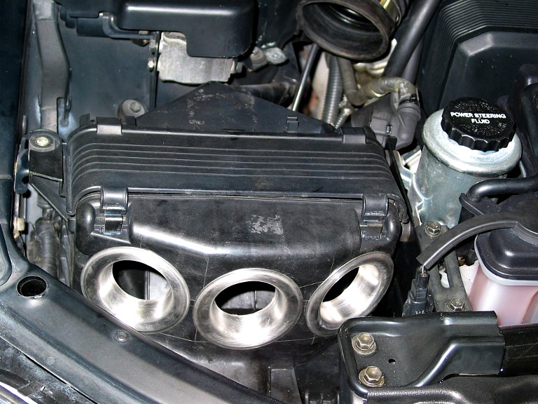
So here is the airbox with two bellmouths - looks great - much better than stock airbox - but pressure drop was still too big - so 2 is not enough - I installed three of them side by side. 3 bellmouths was enough for my hot V8 (140 rwkw). This was measured using the manometer in Siting Cold Air Intakes. I don't know if three will be enough for a supercharged V8 or hot TT - but for now it is plenty and looks great.
Here is the airbox with three bellmouths. They are held in place with hot melt glue. I used a holesaw - an attachment for a drill - bring the eggcup with you to the hardware store to estimate the right size if you need to buy one. Make the hole big enough for the eggcup to move around so you can line them up nicely.
So that takes car of the airbox - if it doesn't flow enough enough when the supercharger goes on then it will have to be changed probably, but for now it does a great job.
It's a shame you don't see them with the top cover in place!
A lot of people stop after doing the hard work with the airbox and don't worry about the final two chambers of the BFI. The 1st and 2nd chambers of the BFI are the easiest AND contribute significantly to the overall performance of the BFI. It is these chambers that give the ram air effect and pressurise the whole intake system - well worth that little bit of extra effort.
The middle chamber or under headlight chamber is essential on the Twin Turbo and UZZ32 Active V8 models - both of these cars have intercoolers below the headlight, air for the TT and suspension oil for the '32. Other Soarers also benefit by ease of installation, increased pressure and crud reduction compared to taking air from below headlight.
In BFI 1 I used plywood and foam. In BFI 2 I used corflute cut and folded to shape. In BFI 3 I am using a flat bottom chamber with no air deflector - this is a further safeguard against getting bugs in the filter.
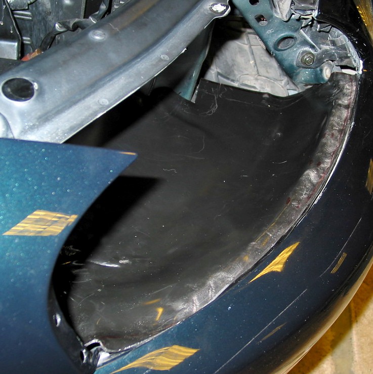
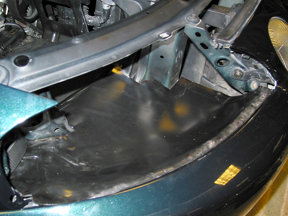
I have sealed the underheadlight chamber with a thin layer of fibreglass on top of some plastic sheets. I have left a corner "pocket" to collect bugs and stuff - rather than a curved deflector like before. The first chamber removes most of the crud with is circular air flow action and sloping drain back entry point. This second chamber may help with the bigger bugs - water has never been a problem - even following trucks on rain soaked freeways the filter stays dry.
Air is still taken from under the licence plate - no changes there.
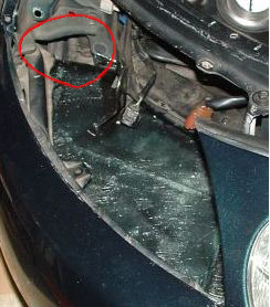
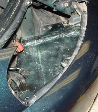
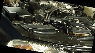
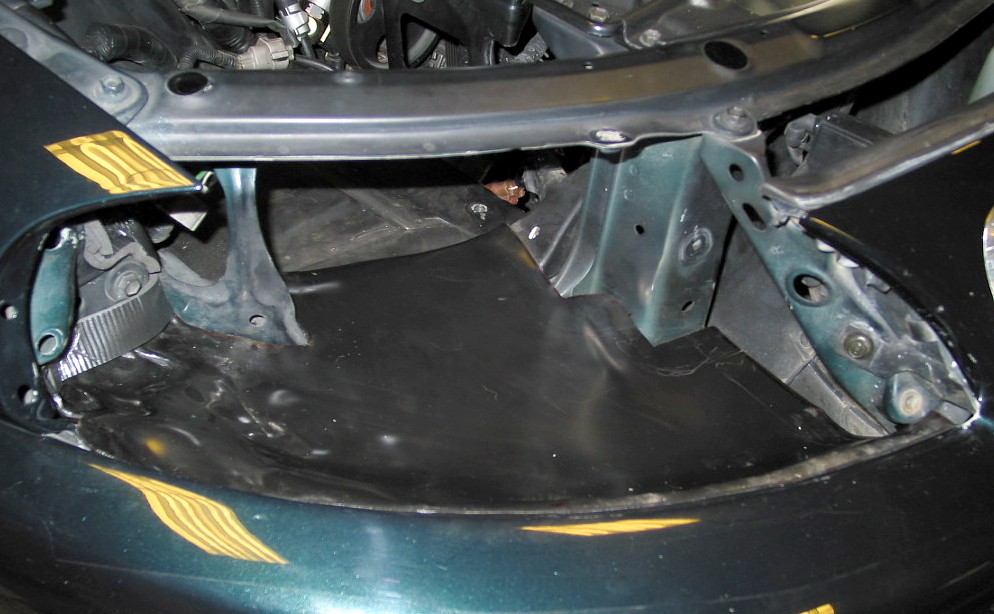
Here are a couple of shots of the chamber under the headlight. It started out as a couple of sheets of plastic like the top cover - not just 1 sheet because it's too hard to fit in. I made a cardboard template the same way as the top cover. Then I pulled it out and cut it in half following the curve of the bumper bar. Then I traced two bits of plastic out with an overlap of about a inch and inserted 1 piece at a time. I was going to screw them together so they would stay in place but decided to fibreglass them in the end and be done with it.
The area circled in red has been covered with plastic as well. This is where I imagine any bugs or crud still in air stream will collect - I'll have another look and see how things are going.
FOR UZZ31 MODELS ONLY!
The airbag UZZ31 has a small valve body mounted just to the left of the foglight. It
sticks up a bit and prevents a flat bottom. The two I have worked on so far were a bit
rushed and we ended up making a bump in the floor of the chamber to accommodate. I still
reckon it would be best to unbolt the body, bolt a plate to it and then bolt the plate
back effectively lowering the whole thing an inch or so. All you would need is a small bit
of plate and a couple of 10 mm bolts and nuts.
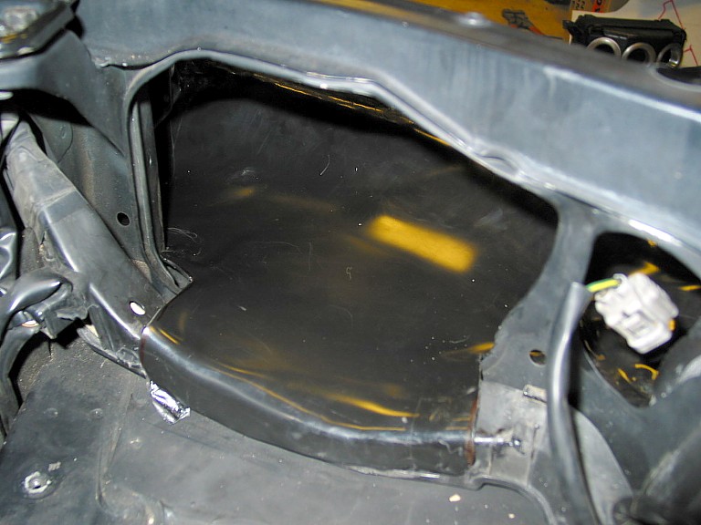
The intake chamber is great. It is large and contains a large volume of pressurised air just waiting to rush into the airbox when you snap the throttle open. It removes water, bugs and crud from the airstream and promotes maximum flow and pressure. It is important to seal the battery side hole near the headlight - this is a significant air flow loss point - about 20% drop in pressure.
This is looking through the battery side headlight. I have cut this bit of plastic using the same cardboard template method mentioned previously. I fixed it in place using original bolt on the left and a christmas tree plastic plug in an original hole on the right. I had previously used an old t-shirt stuffed down there to seal it - not quite good enough! I had to bend the sight glass pipes for the aircond a little bit - it moved out of the way very easily. Then I had to adjust it and twist it a little bit more to get the headlight in. Not much - just a little tweak to make it all fit. The first chamber is now pretty much sealed. The top is sealed by the two rubber strips - one on the bonnet and one on the radiator support bar.
| By Robert Hayden (The_Boss) on Monday, March 31, 2003 - 09:47 pm: |
I did my BFI over the weekend. This is how it went.
First manufacture the stainless trumpets from egg cups by lopping the top off.
Then carefully line up the three trumpets and drill three large holes of the correct size. Mount the trumpets with hot melt glue or construction adhesive (liquid nails etc - hot melt glue may melt on hot days).
Thats stage one done.
The next part was more difficult. Using a peice of 2mm ABS sheet that formed reasonably well with a good heat gun, I moulded the sheet into a scooped flat plate that fills the entire area under the headlight and has a tab that heads under the triangulated cross brace towards the centre of the grille.
This plate also has a section that goes toward the air box and clibs over the plastic trunking that holds the wires below the airbox. This ensures that it can't move.
 Then fill in
along the sides and make a top cover that fits nicely and there you have it.
Then fill in
along the sides and make a top cover that fits nicely and there you have it.
I still have a few hours to go on my top cover, but first run on the dyno showed about 2.5
RWKW improvement. (3.3 rwhp stationary - more when moving over 30 kph)
| By Trevor Taun (Trev) on Saturday, April 12, 2003 - 06:48 pm: |
Well guys I went on the dyno to day and was really blown away!!! The last time I went on this dyno I only achieved 128.4KW,as a stock std V8,well this time I clocked 139.9KW!!! and the only mod I have done is the BFI and changed the oil.