Daniele Bortoluzzi
The intake process strongly influences the performance of an alternative engine, because the power generated depends on the capability of elaborating a large mass flow. For this reason, especially in the field of high output engines, several devices and solutions are introduced in order to improve the fluid mass aspirated during the suction stroke. The ratio between the effective and the ideal aspirated gas masses is defined volumetric efficiency: the engine output, in terms of delivered torque, is proportional to such quantity.
The volumetric efficiency of an engine depends both on quasi-static phenomena, like viscous losses and charge heating, and on typical dynamic phenomena, connected to the pulsating nature of the compressible fluid flow and overall defined "acoustic phenomena". The acoustic phenomena become more and more important as the engine speeds grows, so they are exploited in high speed engines (for example, F1).
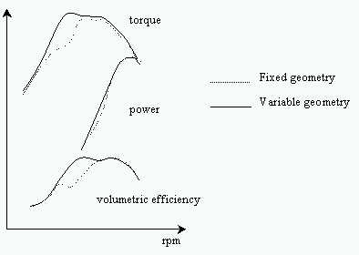
The acoustic phenomena can improve or worsen the cylinder filling according to the engine rpm, so it is important to optimize them at the speed of interest (with a tuned fixed-geometry intake manifold) or in the whole working interval (with a tuned variable-geometry intake manifold, see figure). The variable-geometry intake systems are normally realized modifying the inlet duct length in different ways (continuous or discrete). The solution studied is the modification of the acoustic behaviour of the intake system by adding some Helmholtz resonators to the manifolds and varying their characteristics according to the current engine speed, in order to maximize the cylinder filling at the different speeds.
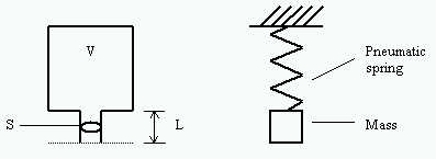
An Helmholtz resonator is constituted by a cavity and a short duct, which connects it to the system. It behaves like a system composed by a pneumatic spring (the cavity) and a mass (the gas inside the short duct): in consequence, it has a natural frequency of pressure oscillations which can be calculated as follows:
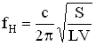
where c is the speed of sound. The resonators are utilized in the field of acoustics to control the sound pressure level inside cavities (rooms, boxes, machine cavities) or ducts ( conditioning, ventilation, exhaust systems), and their efficiency is largely proved and experimented. The utilization proposed is to exploit the acoustic possibilities to interfere with a process of mass transfer, that is, changing the natural frequencies of the intake system according to the current frequency of the alternative movement of the piston.
The intake system without any resonator, composed by the cylinder (spring) and a simple intake duct (mass), can be seen like an Helmholtz resonator, whose resonance frequency is given by the equation above (the volume to consider is the mean cylinder volume, and the length should be corrected considering the little mass of gas outside the duct that moves together with the inner one). The optimum filling is obtained when the natural frequency is about double the piston frequency, and the torque curve shows only one peak.
The intake system with the resonators can be studied with several models, which are able to take into account different fluid dynamic phenomena which take place in the manifolds. Two methods are considered:
- lumped element method, which considers the fluid in a duct like a single mass and the gas in a cavity like a pneumatic spring (example above);
- numerical simulations by means of a finite-difference code.
The agreement between the lumped element method (which is very useful and easily-handled) and the numerical simulations, in terms of possibilities of a resonator-provided intake system, is good. In consequence, it is possible to add one or more resonators in different positions (in-line with the intake manifolds or side-branch) and predict the behaviour of the filling of the cylinder at the different engine speeds.
A "filling index" lV is defined as the ratio between the volume of the fluid which enters the cylinder and the volume generated by the piston stroke. The models above mentioned give some indications on the acoustic phenomena contribution to the filling index. The lumped element model provides the function lV, which depends on the following quantities:
The following figure shows an example of an intake system with an in-line resonator, for a single cylinder engine. The whole intake system behaves like a double Helmholtz resonator, being constituted by two ducts and two volumes. Choosing the dimensions of the pipes, it is possible to calculate the behaviour of the filling index lV varying the piston speed Np [rpm] and the ratio RV between the volume of the cylinder and the volume of the resonator. The figure below shows the lumped element equivalent system.
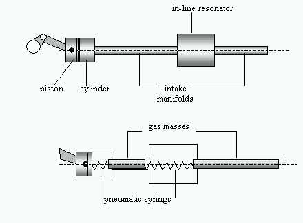
The presence of the second spring adds a second natural frequency and the two frequencies can be calculated as follows:
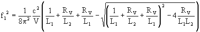

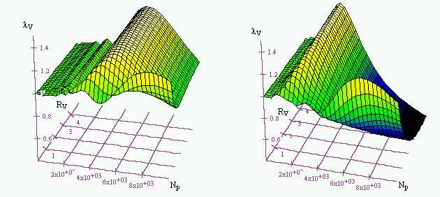
where L1 and L2 are the length-to-area ratios of the two ducts (respectively, attached to the cylinder and open to the atmosphere). With two resonance frequencies the torque curve can show two different peaks, and the optimum piston speeds are near to half the natural frequencies. The following figures show the filling index of two examples relating to different geometries. In the first case the optimum speed of the system without resonator (low values of the volume of the resonator, which give high values of RV) is split into two different speeds by increasing its volume (decreasing values of RV). In the second case, the presence of a resonator favours the filling only at high speeds, worsening it at low speeds: a continuous regulation of the resonator volume in dependence on the rpm would be advisable.
All the geometric configurations can be tested by this method in little time and with the possibility to change in a parametric way any characteristic of the system (volumes, lengths, cross-sections), in order to find the best solution, which can be a variable-volume or variable-duct-section resonator. The goal could be to improve the filling (i.e. the torque) at a certain rpm (for example, to contrast some negative pressure-wave effects) or in an interval of engine speeds (to improve the whole power delivery curve).
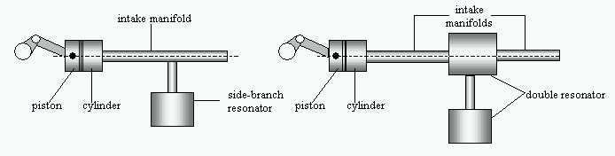
The following figures show an example of an intake system with a side-branch resonator and with a double resonator (composed by an in-line and a side-branch resonator). The best solution has to be found according to the requirements of the engine output but, of course, must also consider the room availability.
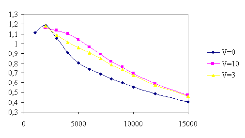
The graph shows the results of some numerical simulations of an intake system with a resonator. It is reported the filling index lV versus the engine rpm, for three values of the resonator volume (V is the ratio between such volume and the cylinder volume, i.e. the inverse of RV). The presence of the resonator is positive at high speeds, and the effect increases with its volume.
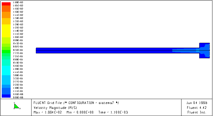
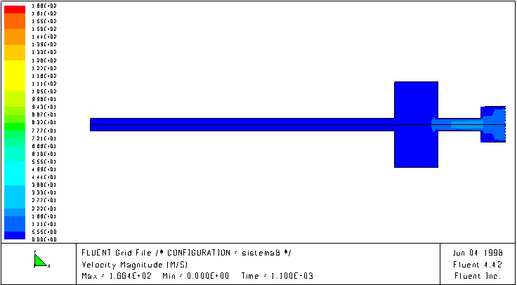
The following figures show the velocity magnitude field inside an intake system without and with an in series resonator, at a certain speed (4000 rpm). It is evident that in presence of the resonator the fluid better follows the piston motion, while in the system without resonator the fluid moves with a lag that limits the mass transfer inside the cylinder.